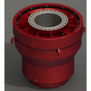
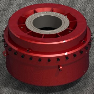
Ram BOP
Description
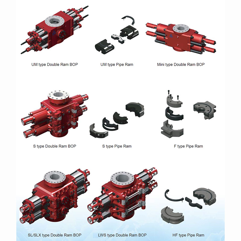
The Ram BOP manufactured has U type, UM type, Mini U type and S type.The design and manufacturing of Ram BOP meets the requirement of API 16A and GB/T20174. The Ram BOP is equipped with Ram of various kinds of size and specification.
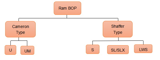
U type Ram BOP adopts the most advanced ram structure of obround, all of its seals adopt high quality rubber, has good sealing performance. It has features of simple structure, beautiful appearance, easy operation, convenient maintenance.
S type Ram BOP has the feature of small volume and light weight.
Features of U type, UM type and Mini U type Ram BOP
Pressure part is forging, has better strength and impact toughness, avoiding of the defects of casting;
Intermediate flange adopts radial floating seal, open and close by hydraulic pressure, changing of ram is fast and convenient;
Equipped with tandem booster, compared with traditional Ram BOP with shearing capacity, the new one is smaller and function of which is constant;
Abundant reserve of ram packer, adopts self sealing;
Manual Locking Device is standard configuration, ensure the ram keep closing in case of hydraulic pressure loss;
Manual Locking Device, Hydraulic Locking Device, and Tandem Booster can be configured at corresponding place according to client’s requirements, and its interchange is convenient.
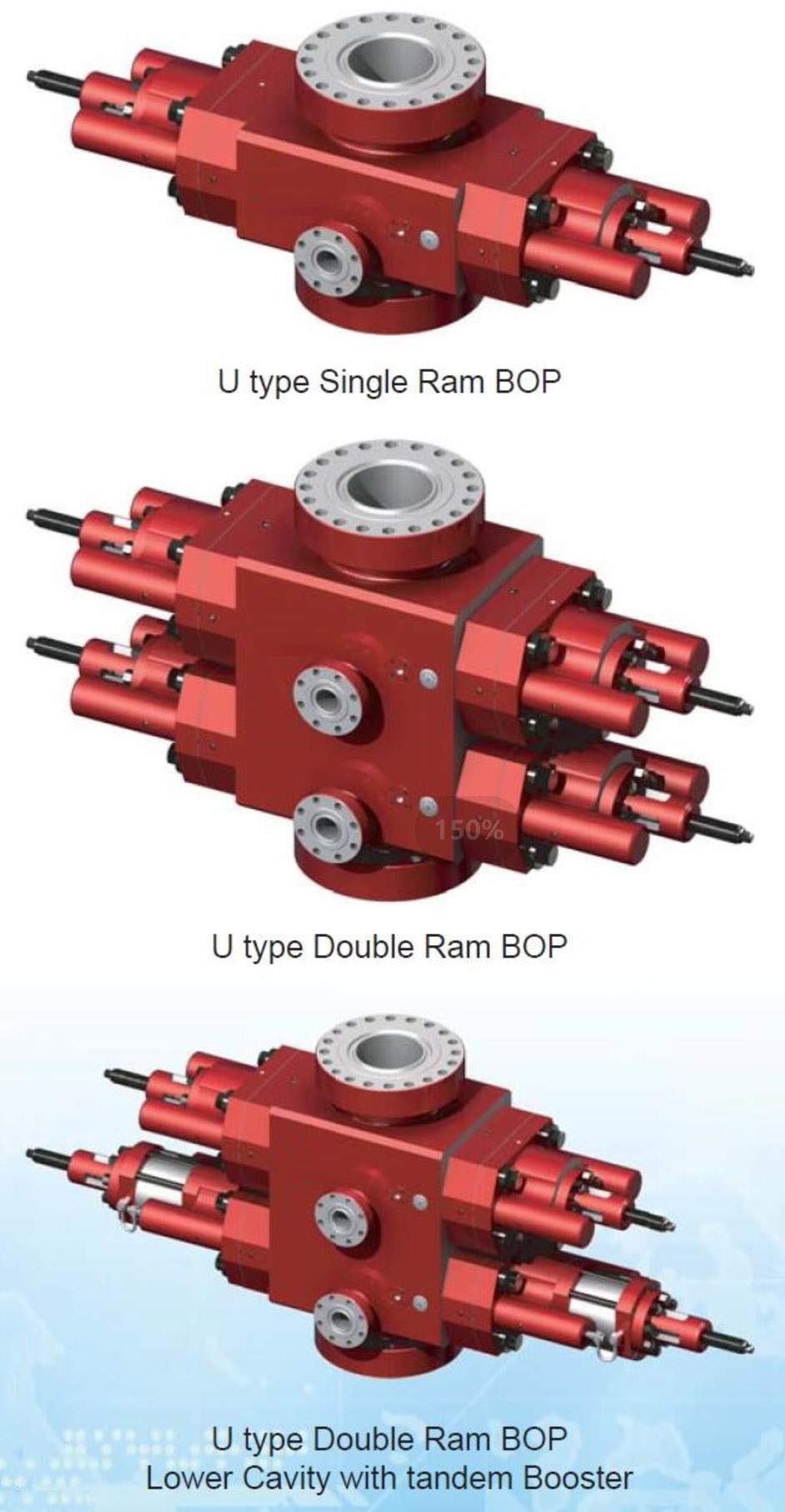
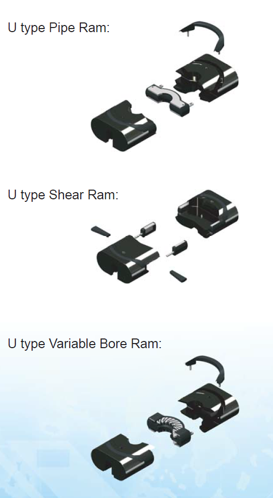
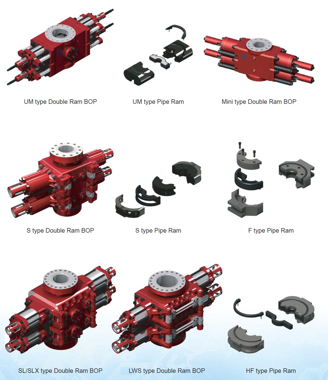
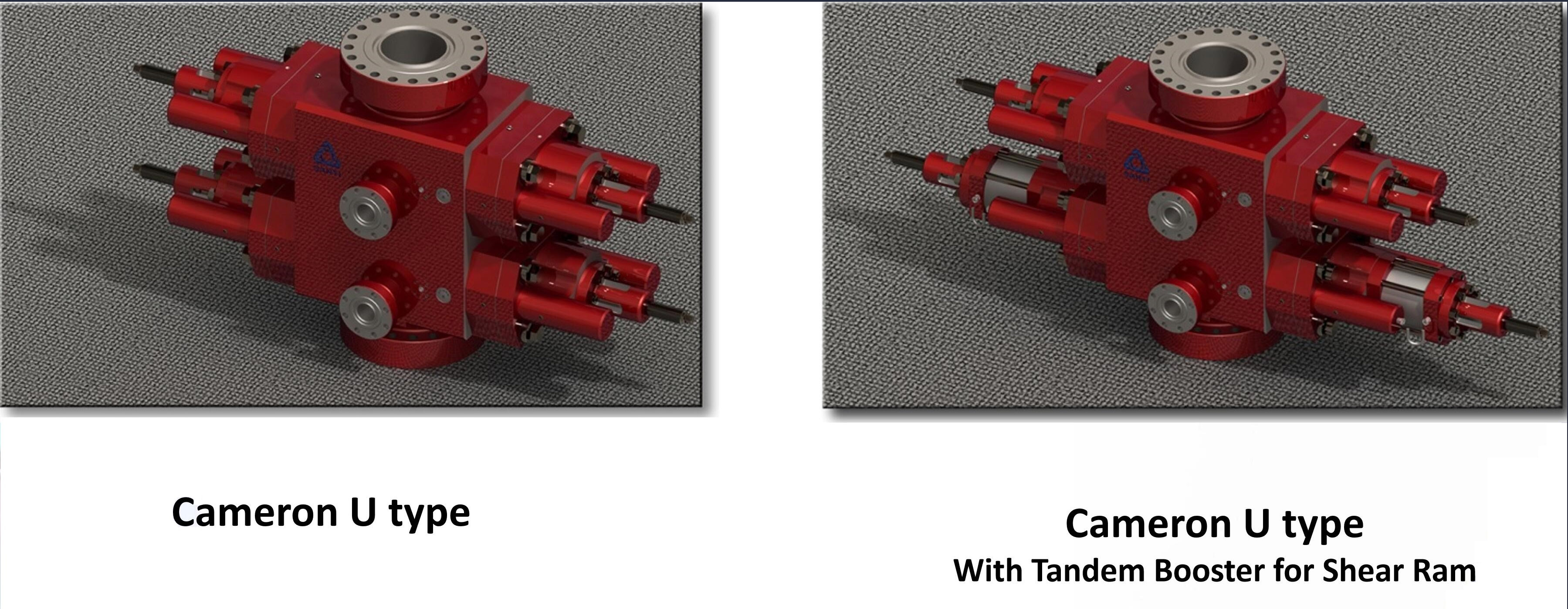
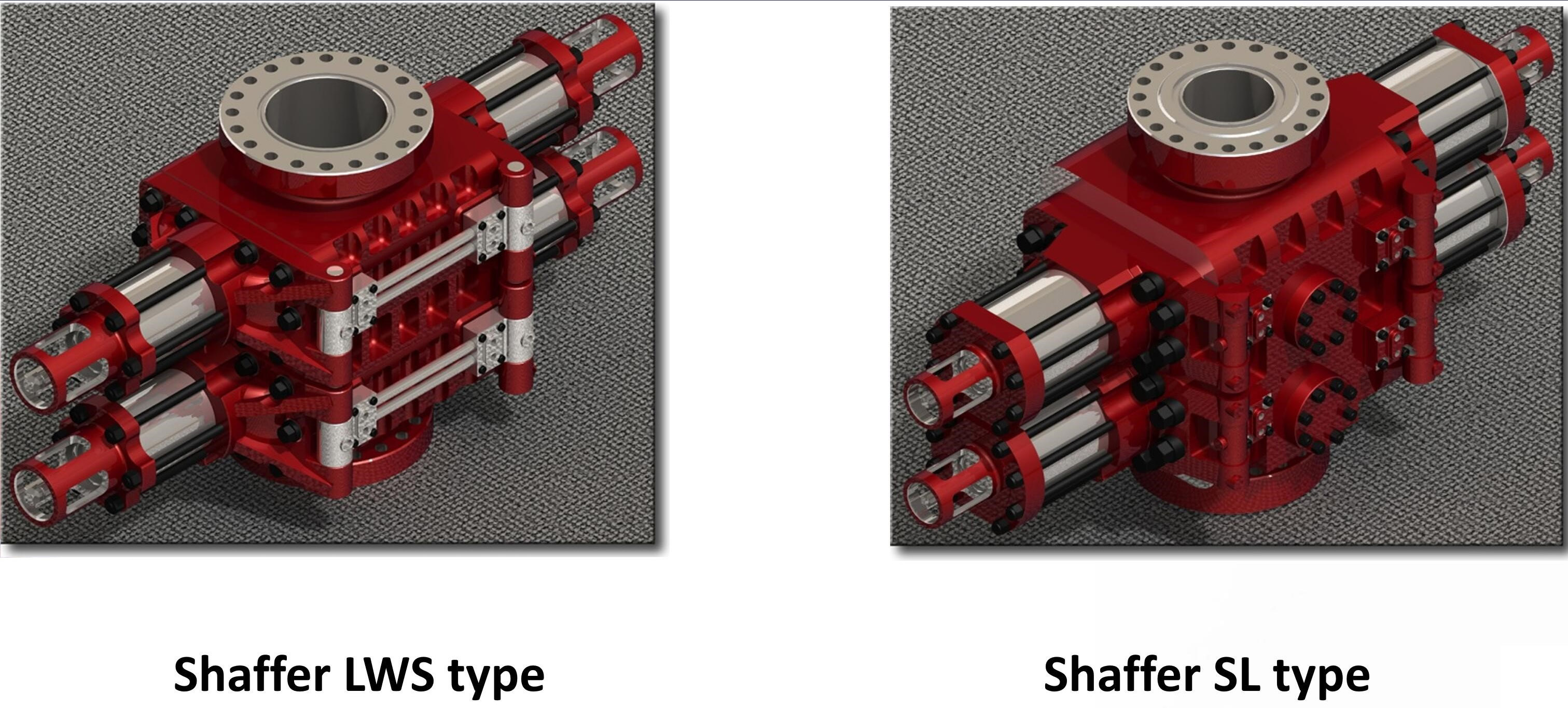
The U blowout preventer is designed so that hydraulic pressure opens and closes the rams and provides the means for quick ram change-out.
Ram closing pressure closes the rams. When the bonnet bolts are removed, closing pressure opens the bonnet. After the bonnet has moved to the fully extended position, the ram is clear of the body. An eyebolt can be installed in the top of each ram to lift it out of the preventer.
Ram opening pressure opens the rams. Following ram change-out, this pressure closes the bonnets. The rams are pulled outward, near the bonnets, before the bonnets begin moving toward the preventer body. This assures that the rams never obstruct the bore or interfere with the pipe in the hole. Hydraulic pressure draws the bonnets tightly against the preventer body and the bonnet bolts are reinstalled to hold the bonnets closed.
Ram BOP Size and Models
|
Working Pressure (PSI) |
7 1/16” |
11” |
13 5/8” |
20 3/4” |
21 1/4” |
26 3/4” |
|
15000 |
U |
U |
U |
- |
-- |
- |
|
10000 |
U |
U & UM |
U & UM |
U |
- |
- |
|
5000 |
U & S |
U,UM & S |
U, UM & S |
- |
U |
- |
|
3000 |
U & S |
U & S |
U & S |
- |
- |
- |
|
2000 |
- |
- |
- |
- |
U |
U |
Note: S – Shaffer type U – Cameron U type UM – Cameron UM type
U BOP Operating Data and Fluid Requirements
|
Bore Size and Working Pressure |
Gals to Open Pipe Rams (1 Set) |
Gals to Close Pipe Rams (1 Set) |
Locking Screw Turns (Each End) |
Closing Ratio |
Opening Ratio |
|
7-1/16” All WP |
1.3 |
1.3 |
18 |
6.9:1 |
2.2:1 |
|
11” Except 15,000 psi |
3.4 |
3.5 |
27 |
7.3:1 |
2.5:1 |
|
11” 15,000 psi |
5.7 |
5.8 |
32 |
9.8:1 |
2.2:1 |
|
13-5/8” Except 15,000 psi |
5.5 |
5.8 |
32 |
7.0:1 |
2.3:1 |
|
18-3/4” 10,000psi |
21.3 |
23.1 |
54 |
7.4:1 |
3.7:1 |
|
20-3/4” 3000 psi |
8.1 |
8.7 |
46 |
7.0:1 |
1.3:1 |
|
21-1/4” 2000 psi |
9.0 |
8.7 |
46 |
7.0:1 |
1.3:1 |
|
21-1/4” 5000 psi |
27.3 |
30.0 |
54 |
7.2:1 |
4.0:1 |
|
26-3/4” 3000 psi |
10.1 |
10.8 |
58 |
7.0:1 |
1.0:1 |
Large Bore Shear Bonnet Operating Data and Fluid Requirements
|
Bore Size and Working Pressure |
Gals to Open Pipe Rams (1 Set) |
Gals to Close Pipe Rams (1 Set) |
Locking Screw Turns (Each End) |
Closing Ratio |
Opening Ratio |
|
7-1/16” All WP |
- |
- |
- |
- |
- |
|
11” Except 15,000 psi |
6.8 |
7.0 |
27 |
12.0:1 |
4.8:1 |
|
11” 15,000 psi |
8.9 |
9.0 |
32 |
15.2:1 |
3.7:1 |
|
13-5/8” Except 15,000 psi |
10.5 |
10.9 |
32 |
10.8:1 |
4.5:1 |
|
18-3/4” 10,000psi |
27.6 |
38.1 |
54 |
14.8:1 |
4.1:1 |
|
20-3/4” 3000 psi |
14.3 |
14.9 |
46 |
10.8:1 |
1.7:1 |
|
21-1/4” 2000 psi |
14.3 |
14.9 |
46 |
10.8:1 |
1.7:1 |
|
21-1/4” 5000 psi |
- |
- |
- |
- |
- |
|
26-3/4” 3000 psi |
- |
- |
- |
- |
- |
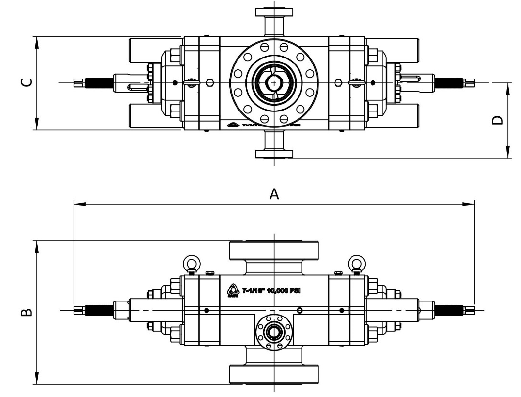
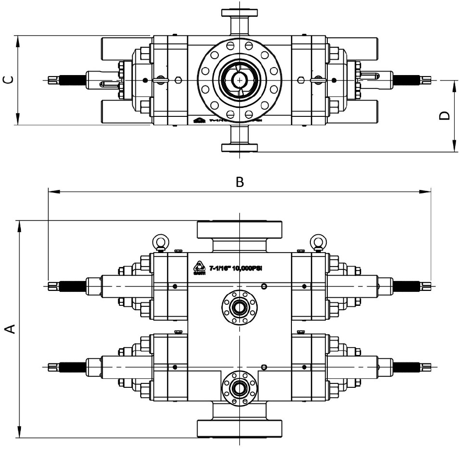
The capital letters in the following designations refer to the U BOP dimensional views and dimensional
charts shown on the following pages.
A-1 Length – bonnets closed, locking screws locked
A-2 Length – bonnets opened, locking screws unlocked
B-1 Height – Flanged connection
B-2 Height – Studded top, flanged bottom
C Width – No side outlets
D Distance from BOP Centerline to outlet flange surface. It is changed as per different
specifications. (no data for this item in the table)
Note: Weights are based on forgings.
Dimensional Drawing of Single Ram BOP, Type U
|
Size (in.) |
Pressure Rating(psi) |
A-1 (mm) |
A-2 (mm) |
B-1 (mm) |
B-2 (mm) |
C (mm) |
Weight (Kg) |
|
7-1/16 |
3000 |
1943.0 |
2213.0 |
614.0 |
488.0 |
508.0 |
1380 |
|
7-1/16 |
5000 |
1943.0 |
2213.0 |
698.0 |
559.0 |
508.0 |
1435 |
|
7-1/16 |
10,000 |
1943.0 |
2213.0 |
776.0 |
606.0 |
508.0 |
1850 |
|
7-1/16 |
15,000 |
1820.0 |
2059.0 |
812.0 |
651.0 |
520.0 |
1950 |
|
11 |
3000 |
2310.0 |
2710.0 |
750.0 |
600.0 |
610.0 |
2850 |
|
11 |
5000 |
2310.0 |
2710.0 |
862.0 |
688.0 |
610.0 |
2950 |
|
11 |
10,000 |
2444.0 |
2794.0 |
908.0 |
718.0 |
640.0 |
3600 |
|
11 |
15,000 |
3040.0 |
3462.0 |
1140.0 |
956.0 |
812.0 |
6700 |
|
13-5/8 |
3000 |
2790.0 |
3224.0 |
860.0 |
750.0 |
680.0 |
4220 |
|
13-5/8 |
5000 |
2790.0 |
3224.0 |
900.00 |
770.0 |
680.0 |
4360 |
|
13-5/8 |
10,000 |
2850.0 |
3298.5 |
1060.0 |
855.0 |
768.0 |
5915 |
|
13-5/8 |
15,000 |
3670.0 |
3929.0 |
1324.0 |
996.0 |
4003.0 |
12600 |
|
18-3/4 |
10,000 |
4570.0 |
6070.0 |
1422.0 |
1172.0 |
1079.5 |
14365 |
|
20-3/4 |
3000 |
3656.0 |
4252.0 |
1000.0 |
742.0 |
1007.0 |
8000 |
|
21-1/4 |
2000 |
3664.0 |
4260.0 |
914.0 |
785.0 |
1004.0 |
7880 |
|
21-1/4 |
5000 |
4872.0 |
6351.0 |
1296 |
- |
1080.0 |
13435 |
|
26-3/4 |
3000 |
4309.0 |
699.50 |
1227.0 |
- |
1175.0 |
13760 |
Dimensional Drawing of Double Ram BOP, Type U
|
Size (in.) |
Pressure Rating(psi) |
A-1 (mm) |
A-2 (mm) |
B-1 (mm) |
B-2 (mm) |
C (mm) |
Weight (Kg) |
|
7-1/16 |
3000 |
1943.0 |
2213.0 |
1038.0 |
914.0 |
508.0 |
2925 |
|
7-1/16 |
5000 |
1943.0 |
2213.0 |
1126.0 |
914.0 |
508.0 |
2980 |
|
7-1/16 |
10,000 |
1943.0 |
2213.0 |
1187.0 |
1017.5 |
508.0 |
3430 |
|
7-1/16 |
15,000 |
1820.0 |
2059.0 |
1222.0 |
1061.0 |
520.0 |
3500 |
|
11 |
3000 |
2310.0 |
2710.0 |
1262.0 |
1114.0 |
610.0 |
5600 |
|
11 |
5000 |
2310.0 |
2710.0 |
1374.0 |
1200.0 |
610.0 |
5700 |
|
11 |
10,000 |
2444.0 |
2794.0 |
1420.0 |
1230.0 |
640.0 |
6550 |
|
11 |
15,000 |
3040.0 |
3462.0 |
1774.0 |
1590.0 |
812.0 |
12470 |
|
13-5/8 |
3000 |
2790.0 |
3224.0 |
1410.0 |
1300.0 |
680.0 |
8450 |
|
13-5/8 |
5000 |
2790.0 |
3224.0 |
1450.0 |
1320.0 |
680.0 |
8560 |
|
13-5/8 |
10,000 |
2850.0 |
3298.5 |
1717.0 |
1455.0 |
768.0 |
11985 |
|
13-5/8 |
15,000 |
3670.0 |
3929.0 |
2038.0 |
1710.0 |
1003.0 |
22640 |
|
18-3/4 |
10,000 |
4570.0 |
6070.0 |
1422.0 |
1172.0 |
1079.5 |
27680 |
|
20-3/4 |
3000 |
3656.0 |
4252.0 |
1650.0 |
1392.0 |
1007.0 |
16800 |
|
21-1/4 |
2000 |
3664.0 |
4260.0 |
1564.0 |
1435.0 |
1004.0 |
16700 |
|
21-1/4 |
5000 |
4872.0 |
6351.0 |
2094.0 |
- |
1080.0 |
25770 |
|
26-3/4 |
3000 |
4309.0 |
699.50 |
2003.0 |
- |
1175.0 |
27270 |

